OBM-U4K Series
Postium OBM-U 시리즈는 UHD/4K 제작 및 방송 QC 모니터링을 위해 설계되었으며 9인치, 24인치, 55인치의 두 가지 모델이 포함됩니다. OBM-U090은 UHD/4K 신호를 기본 1920×1080 해상도로 축소하여 표시합니다. U550L은 기본 3840×2160 UHD 해상도를 활용합니다.
두 모델 모두 표준 12G/6G/3G-SDI 입력 인터페이스(x2)와 HDMI®2.0 입력을 갖추고 있으며 SDI 및 SFP를 통해 4K Quad Link 2-Sample Interleave 및 4K Quad Link Square Division 신호를 모두 지원합니다(OBM-U090에는 SFP 입력 없음). 아날로그 컴포지트/컴포넌트 I/O는 OBM-U090에서만 지원됩니다.
CEA-708(HD-SDI 자막 표준) 및 CEA-608(SD-SDI 자막 표준)에 대한 자막 디코딩 및 표시 표준)은 SDI 입력을 통해 지원됩니다. OBM-U 시리즈는 최대 3840×2160/24,25,30,50,60p 및 4096×2160/24.25.30,50,60p 신호를 수용합니다.


Key Features of 4K IP Monitors
· 12G SDI Quad Link 8K / 12G-SDI Single Link 4K
· 6G-SDI Dual Link 2-S.I. 4K
· 3G-SDI Quad Link Square Division 4K / 3G-SDI Quad Link 2-Sample Interleave (2-S.I.) 4K
· Dual SFP Module Inputs (ST 2022-6 Support)
· HDMI® 2.0 Input
· HDR(High Dynamic Range) Display supporting PQ (ST 2084), Hybrid Log Gamma, S-Log3
· Wide Color Gamut Supporting ITU-R BT.709, SMPTE-C, EBU, Native, DCI-P3, ITU-R BT.2020
· Internal color processing 72bit(24bitx3) + Native 33x33x33 30bit 3D-LUT
· 1.073 Billion Colors
· Gamut Error
· Black stretch
· Camera Log Conversion
· Custom 3D LUT file Import Through USB
· Gamma Selection (1.0 ~ 3.0)
· SDR EOTF - BT.1886 (Gamma 2.4)
· Color Temperature (3200K, 5500K, 6500K, 9300K, USER 1/2/3, D-CINEMA)
· Monitor Control via Ethernet, RS-422
· Image Division & Link Order Auto Detection
· Waveform, VectorScope (Wave + Vector)
· HDR Waveform
· Various Markers (EBU, 4:3, 16:9, 1.85:1, 2.35:1, Variable Custom)
· Zero Scan
· Time Code Display
· De-embedded 8~16ch Audio Level Meter
· Internal Pattern Display for Color Test (Black ~ 100% White, Color Bar)
· Remote Control via GPI(RJ-45) Port
· False Color : Zebra, Color Pattern, ARRI
· Easy Firmware Update by USB
· System Data Copy
· H/V Delay
· Blue/Mono Only
· Focus Assist
· 3 Color TALLY Lamp
· HDR Auto Setting
· Aspect
· Freeze
Display Functions
Wide Color Space Support including DCI-P3 and ITU-R BT.2020 is controlled with an advanced 3D LUT (Look Up Table) to reproduce various color spaces accurately with smooth, artifact-free grayscale steps. Available color gamuts are DCI-P3, ITU-R BT.2020, ITU-R BT.709, SMPTE-C, EBU, and Native.

Versatile 4K/QFHD Input Capability
The OBM-4KIP series is equipped with standard 12G-SDI input interface(x4) and support 4K/8K Quad Link 2-sample inter-leave signals and 4K Quad Link Square Division signals.
The OBM-4KIP Series can accept up to 7680×4320/23.98,24,25,29.97,30,50,59.94,60p and 8192×4320/23.98, 24, 25, 29.97, 30, 50, 59.94, 60p.

Custom 3D LUT File Import
The OBM-4KIP Series allow the user to import 3D Look-up Table for accurate and consistent color match- ing between indivisual displays as well as using customized ‘looks’ that have been created by 3rd party color-grading applications. 32^3, 33^3, 64^3 and 65^3 cube file is supported.

Camera Log Selection
The OBM-4KIP series have the built-in camera LUT of the various camera manufacturers. It allows users to load the following camera logs. Log-C, C-Log / S-Log2, S-Log3 / J-Log1
The more camera LUTs will be updated.

High Dynamic Range(HDR) Display Function
The OBM OBM-4KIP series provides the function to display the High Dynamic Range footage.
Postium HDR function allows users to view both highlights and shadow detail of scenes at the same time, thus resulting in more natural and realistic images.
The OBM U**8K/4K series supports PQ EOTF (SMPTE ST 2084), Hybrid Log Gamma and S-Log3.
HDR Mode
SDR Mode

Focus Assist
Focus Assist controls the aperture level of a video signal and displays images on screen with sharpened edges to help camera focus operation.

4K HDR Waveform Monitor and Vector Scope Display
modes enable users to monitor sources using the internal Waveform and Vector Scope individually or simultaneously.

The position of Waveform and Vector Scope can be moved between Top Left, Top Right, Bottom Right, and Bottom Left.
HDR Mode + HDR Waveform
HDR Waveform

SDR Mode + SDR Waveform
SDR Waveform
Adjustable Gamma
control allows for incremental compensation between gamma correction values of 1.0 and 3.0 — thereby ensuring that the decoded image isn’t too bright (no gamma correction) or too dark (over correction).

Gamma 1.8
Gamma 2.4
4K/QFHD Mode
The LCD panel resolution of OBM-U31IP/24IP is QFHD(16:9) 3840×2160, so if the input signal is 3840×2160 1:1 mapping is supported. If the input signal is DCI 4K(4096×2160), 1:1 mapping is not supported.
[Zero Scan]

Panel 3840x2160(16:9)
Input Image 3840x2025
Panel 3840x2160(16:9)
Input Image 3840x2160
When the 4096×2160 signal is fed, if you select Zero Scan using [Scan] button on the front panel, the picture is scaled to be displayed on the panel of 3840×2025 resolution with maintaining 1.89:1 ratio..
[1:1 Scan]
When 1:1 Scan mode is selected with the [Scan] button in 1920×1080, 1280×720 mode, etc., it is placed in the center of the screen as above. A 1:1 mapped image is output.

Various Frame Markers/Mattes
Various Frame Markers/Mattes are available on the OBM-U series, including aspect, area, and center markers. In addition, the detailed display settings of each marker are allowed. For example, the color, brightness, horizontal/vertical position, and thickness of aspect markers can all be adjusted.

Aspect Mat 5
Display various markers
Custom marker
Input Signal Format Support
Single Link 12G/6G/3G/HD-SDI, Dual-Link 6G/3G-SDI, Quad Link 12G/6G/3G/-SDI signals can be
Input to the SDI In connectors of this monitor.
Up to 4-channel Single Link 12G/6G/3G/HD-SDI signals, 1-channel Dual-Link 6G/3G-SDI or 1-channel Quad-Link 12G/6G/3G-SDI signals can be input. Use the appropriate input connectors depending on the input signal, referring to the table below
Single Link 12G-SDI

Dual Link 2-Sample Interleave(2-SI)
Dual Link 2-Sample Interleave(2-SI)Quad Link 2 Sample Interleave (2SI)
Each link contains a full image at 1/4 resolution. 2SI mode uses four Sub-image and alternates the samples every two pixels and every line instead of slitting the image into four quadrants.
12G-SDI Single Link Square Division Moad
Meets the Return Loss Standard, SMPTE ST 2082-1:2015
In the professional broadcasting video industry, Return Loss is an important parameter that measures the reflected signal that bounces back from a terminated device. If the broadcast monitor has the poor return loss, the level of reflected signal negatively impacts the signal integrity of the loop-out signal.
The OBM-U**8K monitors meets the requirements of Return Loss specified in SMPTE ST 2081-1:2015, so that the OBM-U**8K monitors provides the high signal fidelity.

<SMPTE ST 2082-1:2015 Requirements>
12G-SDI (ST 2022-6) over IP is supported in the OBM-U**8K series via an SFP interface, which allows the use of various SFP modules. The OBM-U series monitors can display the 12G-SDI over fiber and the 12G-SDI Single Link over IP through the integrated SFP interface

False Color
False Color indicates the Luma (Y) level of the input image. If a certain Y level is set, the pixels with the designated Luma (Y) level are displayed with a zebra pattern or a color pattern. There are display modes – Zebra, Variable, ARRI, and Comparison.
Zebra
This mode displays the Luma(Y') level of the input image in zebra pattern.
False Color Variable
This mode allows the user to adjust White clipping, Pink level, Green level, Black Clipping.

False Color ARRI
The color pattern is displayed with ARRI camera standard.
False Color Comparison
This function enables the user to divide the picture side by side, and compare the original image on the left half and the False Color image on the right half.
Gamut Error
Gamut Error Type can be observed in 3 modes.
Type 1
when the targeted color space is selected as BT.709, the pixels outside of the targeted color space are displayed as Black Zebra.
The pixels over Y Maximum, Chroma Maximum, RGB Maximum are displayed as Black Zebra, and the pixels below Y Minimum, Chroma Minimum, RGB Minimum are also displayed as Black Zebra.

Type 2
when the targeted color space is selected as BT.709, the pixels outside of the targeted color space are displayed as Black or White Zebra.
The pixels over Y Maximum, Chroma Maximum, RGB Maximum are displayed as Black Zebra, and the pixels below Y Minimum, Chroma Minimum, RGB Minimum are displayed as White Zebra.

Type 3
when the targeted color space is selected as BT.709, the pixels inside of the targeted color space are displayed as Mono, and the pixels outside of the targeted color space are displayed as the color. In this type, black and white area is not recognized.

Black Stretch
Black Stretch increases visibility in dark areas without degradation of image quality in bright areas. This mode can be used to increase shadow detail without changing absolute black level and without affecting mid-tones
Black Stretch Off
Black Stretch On

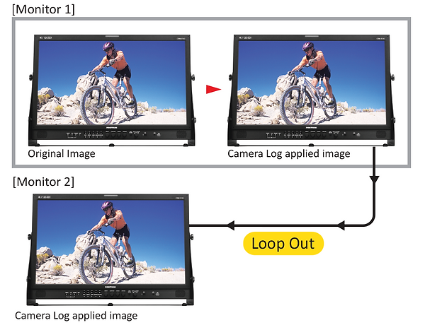
Camera Log Mapped SDI Loopout
This function allows to load the camera log to the original image and then send the camera log mapped image to another monitor through SDI loop out.